Kit for PCB v2.4.2 (from 4ms Pedals)
- PC Board kit building General instructions for building kits with pot-mounting pc boards. Usb драйвер для i8000
- Box drilling template (same as v2.4.1) Каталог

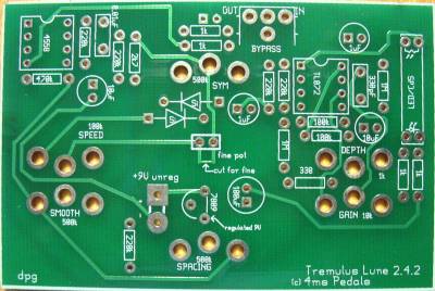
- LEDs: The Bypass LED is located next to the 1k resistors by the Bypass wiring section. The long lead of the LED goes in the square hole. The LED that shines on the photocell is mounted directly to the PCB. The long lead of the LED goes in the hole closest to the TL072 chip (on the left if you’re holding the board so you can read the words). Bend this LED over so it points at the CdS (photocell), which should be mounted so its face is perpendicular to the PCB. одежда для полных женщин москва
Kit for PCB v2.4.1 (from 4ms Pedals)
- PC Board kit building General instructions for building kits with pot-mounting pc boards.
- Schematic includes Symmetry/Fine jumpers
- Note: the kit from 4ms Pedal normally contains parts for Symmetry instead of Fine Tuning. You may build the pc board either way: see the wiring diagram for instructions
Dual LFO Tremulus
- Uses a Panneur PCB for a mono-in, mono-out tremulus with a second LFO to modulate speed of main LFO
Point-to-Point board (DIY)
- Mods (for point-to-point boards, but may be adapted for PCB 2.4.1)
- Aux LFO (to add) “superboard”
- Combination mod (for aux LFO)
- Tweaker guides
http://educ-envir.org/~euziere/wikini/wiki4/wakka.php?wiki=MIlwaukeeSeoSpecialist http://ferme.euziere.info/wiki01/wakka.php?wiki=MilwaukeeSEOSpecialist http://www.abernet.fr/wakka.php?wiki=MilwaukeeSEO http://www.camargue34.fr/tourisme/wakka.php?wiki=MilwaukeeSEOPrices http://salamandrix.free.fr/wikini/wakka.php?wiki=MilwaukeeSEOPricing http://wikis.cdrflorac.fr/wikis/wiki019/wakka.php?wiki=MilwaukeeSEO
http://pedsovet.org/forum/index.php?autocom=blog&blogid=6747 http://www.leretourdelautruche.com/pmwiki/index.php/Main/Brookfield http://mjc-cs-brianconnais.org/yeswiki/wakka.php?wiki=BroogkfieldSEOSpecialist http://www.adec56.org/yeswiki/wakka.php?wiki=WaukeshaSEO http://relie-toits.org/groupe/wakka.php?wiki=WaukeshaSEO http://wiki.coop-tic.eu/wikis/LHM/wakka.php?wiki=WaukeshaSEO https://en.wikipedia.org/wiki/Brookfield,_Wisconsin#Notable_people http://macommunity.net/entry.php?42-Waukesha-SEO https://www.wildblueworld.com/forum/entry.php?91-Milwaukee-SEO-companies
QUESTION: Is better to use a anti-log pot for lfo frequency??? the standard pot gives a log frequency sweep...
ANSWER: Yes, if you can find an anti-log pot, that’s ideal. Using a log pot and wiring it “backwards” (pins 1&2 instead of 2&3) will give you a nice range, although it’ll be faster-CCW, slower-CW
By “Frequency” you mean “speed,” correct? As labeled on the schematic (there is no frequency pot.) That seems most logical but I’m unclear about what “spacing” does. So Spacing = Frequency? or Speed = Frequency? Thanks