Congratulations on your Bend Matrix kit!
This guide has been updated for PCB version 2.3.3. The photos show version 2.3 which is very similar. Differences between the two will be explained as we go along.
This isn’t a trivial thing to build, but neither is the value of a versatile programmable switching matrix.
Building should be more or less explanatory based on the images, but I’m sure there will be questions. Please use the forum for discussion, including getting help.
If you have any tips etc please post them on this wiki page.
- Go slow
- Be careful
- Look both ways
- Keep your iron clean!
OK Let’s get started!
SOLDER THE BOARD
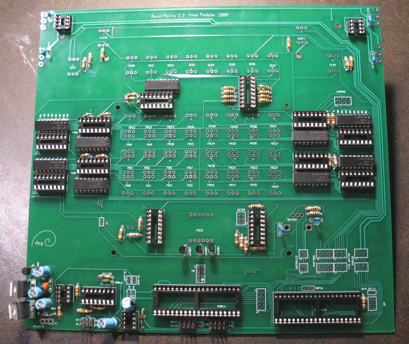
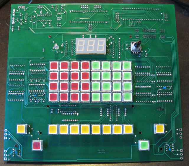
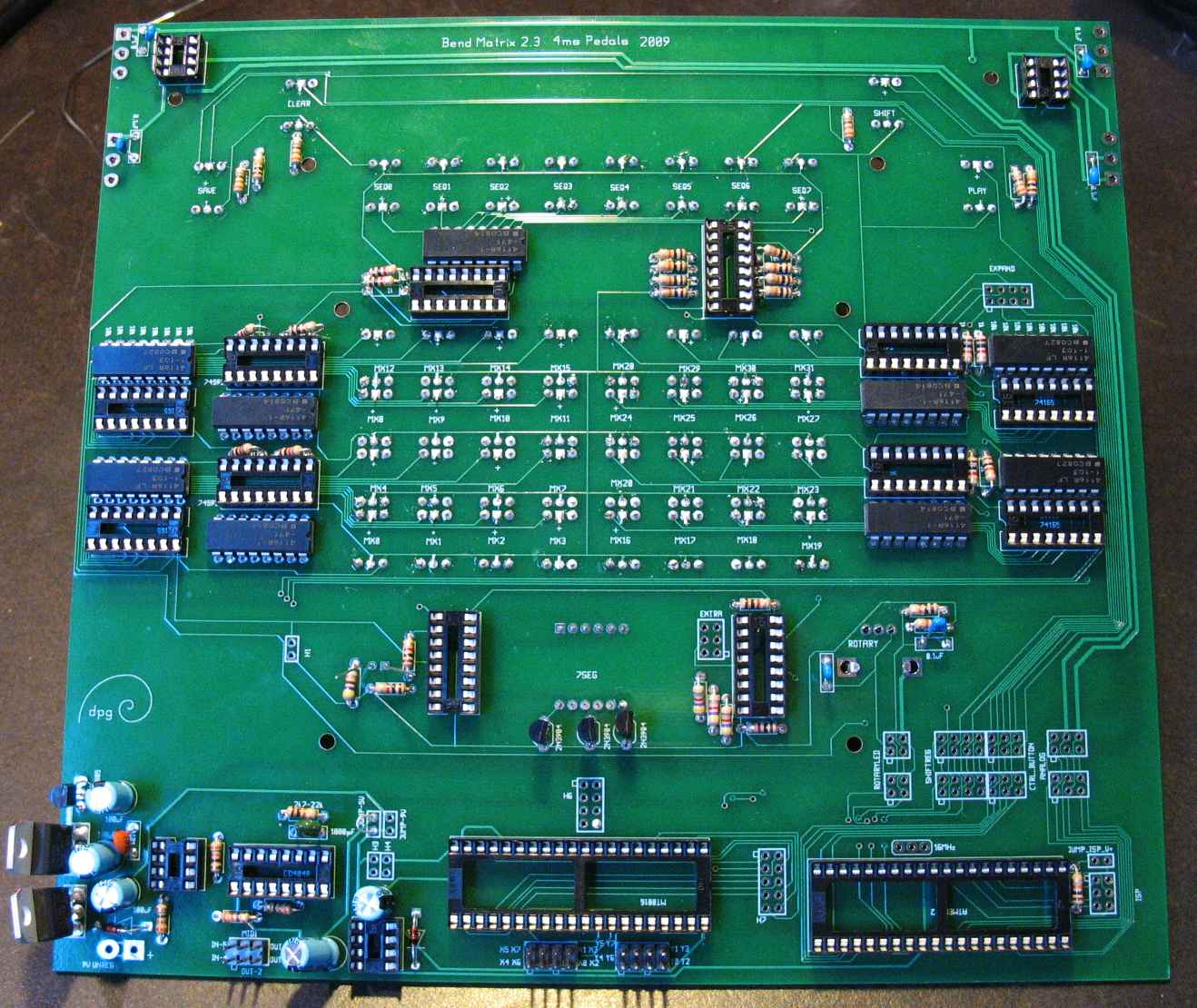
1) Here’s your board:

2) Solder in the IC sockets. Line up the notched end of the socket with the notched outline on the board.

3) Solder the resistors. Note that on the board there are 5 arrays of 470 ohm resistors, and 4 arrays of 10k resistors, each array having 8 resistors. In the photo I’ve used 16-pin resistor array chips that look like ordinary IC chips. No socket is necessary for these resistor array chips. (Alternatively, you can use discrete 1/4W or 1/8W resistors and save a few cents.) The 470 ohm resistor arrays have the number “471” printed somewhere on them, and the 10k’s have “103” printed somewhere on them.

4) Solder the capacitors, diodes, the three transistors, and the three headers (four 8-pin headers, and one 6-pin MIDI header), voltage regulators, and everything else. For PCB version 2.3.3 and newer, make sure to solder a 8MHz crystal resonator near the ATMEGA32 chip. For earlier PCBs, the resonator is optional.
The electrolytic caps (100uF) are directional, so make sure to insert the long lead (+) into the square hole on the board.
5) For PCB v2.3 and older only: See this page.
6) Solder a wire to jump where it says “JUMP 5V”.
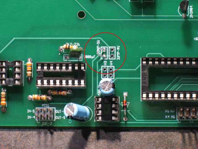
If you are going to hack or re-program your Bend Matrix using an Atmel AVRISPMKII programmer, then solder a wire to jump “JUMP_ISP_V+”. Also solder a 6-pin header into the ISP header footprint (not included in the kit). If you don’t know what this means, or if you want to keep things simple and maybe hack your Bend Matrix later, then just ignore this.
BUTTONS!
7) Take a look at your illuminated buttons. Nifty, huh? The four corner pins connect together when the button is pressed. The slightly smaller center pins are for the LED, one of them is faintly marked with a plus sign (above the “3”). It’s hard to see, but very important to know:

Now that you know which end is + on the LED buttons, go ahead and install them onto the other side of the board (not the same side as the other components). The + pin goes in the square hole. Be careful, the row of 8 sequencer buttons (yellow) are upside down from the rest of the buttons (just to make sure you’re paying attention...)
This is how I like the colors to go (but you can do it any way you like, it’s your bend matrix):

After putting them all in (or as you go along, if they feel loose), bend the middle two pins inward using a fine tip flat-head screwdriver (or your fingernail, but don’t blame me if you poke yourself). The reason you do this is to hold the button in place as well as make a temporary connection to the board so you can test your LEDs before soldering them (read on...). It’s a good idea to press the button firmly to the board with one hand, while you bend the leads over with the other hand, that way the button won’t be at an angle when you let go.

8) Now, we’re going to run some tests before soldering the buttons. This is an optional step, but it could save you TONS of time de-soldering a backwards LED button (they are tightly packed and difficult to pull out). Besides, it’s fun to take a break and make things light up.
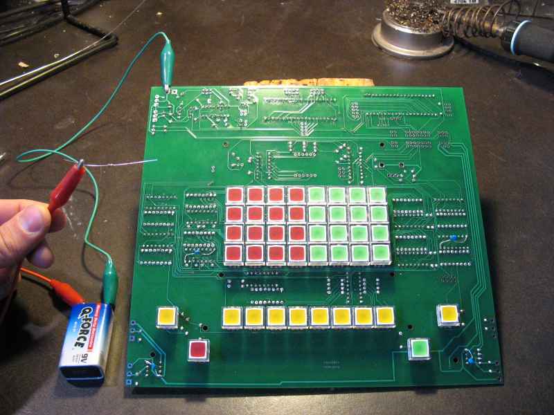
- Get out a 9V battery, or something that outputs 5V or more
- Use an alligator clip or piece of wire to connect the battery’s negative to the ground on the board, which is the circle hole at the top of the board where it says “9V UNREG” (green wire in the photo)
- Connect the battery’s positive to one end of a small resistor, anything between 330 ohms and 5k will work.
- You should look like this:
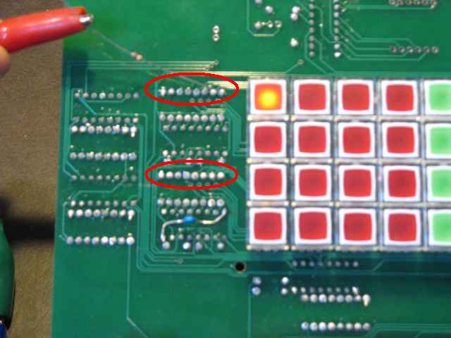
- Now run the other end of the resistor across these two rows of 8 pins each, touching just one point at a time. Each time you touch a point, a different LED should light up. These two rows should cover the 4×4 square of red LED buttons.
- Do the same thing to these two rows:

- One more row to test:

- Test the remaining four buttons just by touching the resistor directly to their bottom center pin
- What if one of the LED buttons doesn’t light up? Could be several reasons:
- Make sure the LED button is making a good connection on both of its LED pins (the middle pins that you bent over). Bend them better, or just wiggle the button while you touch the resistor to its point. If it lights up, even for a millisecond, then you know it’s not in backwards
- If it’s still not lighting up, flip the board over and put the resistor directly to the + pin on the LED. Make sure the - pin is making a good connection to ground.
- If it’s still not lighting up, pull it out. It’s probably backwards. Better to do it now than to have to unsolder it later.
9) Once you’re satisfied all the buttons are in the right way, go ahead and solder them. It’ll look a lot better if they’re all straight, so make sure each one is firmly seated before soldering it. You might want to solder just one or two pins per button, then flip it over and check your work before soldering the rest of the pins.
10) Put on the 7-segment LED display (make sure the decimal point is at the bottom), and the round LED (long lead in the square hole), and the rotary encoder
11) Solder everything and go over the whole board, making sure you didn’t miss any solder joints (it’s easy to do! for extra credit find the one pin I missed in a previous photo...)
MOUNTING
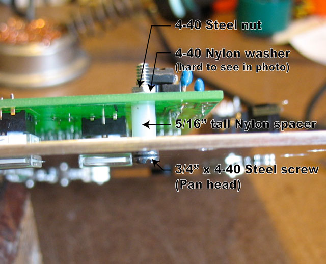
12) If you got a panel with your kit, then mounting it fairly straight forward. There are six 1/8” holes in the pcb that line up with six holes in the panel, and a 3/4” 4-40 screw that connects the two. The head of the screw is on the panel side. Then there’s a 5/16” nylon spacer that goes between the panel and pcb. Then a nylon washer and metal tighten down on the pcb. The spacing should be so that the buttons line up to the outside face of the panel.
If you’re mounting it into your own panel/enclosure, email me to get a layout file for the cut-outs
WIRING
We are going to run wires from the switching matrix chip (MT8816) to jacks. You might be doing something else, like hard-wiring your bend matrix to a circuit-bent project, or to a video mixer, or between your infrared weevil detector and flour sample conveyor belt.... but the concept is the same: we have rows (X’s) and columns (Y’s) of points that get switched together.
PCB version 2.3.2 and newer
(For PCB 2.3.1 and earlier, see this page
The kit includes four rainbow wire cables:
- X0-X3: 13” cable, pin 1 is Blue
- X4-X7: 13” cable, pin 1 is Blue
- Y0-Y3: 9” cable, pin 1 is Brown
- Y4-Y7: 9” cable, pin 1 is Brown
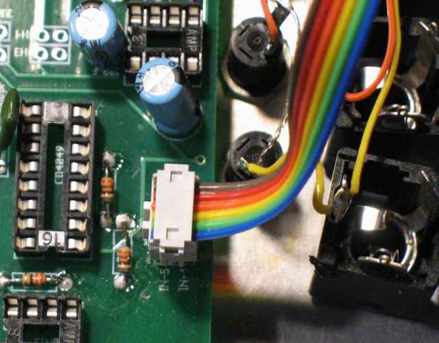
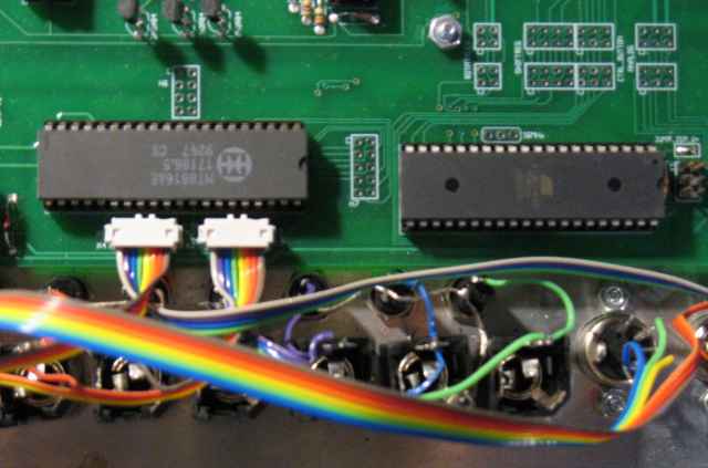
Connect the cables as shown:

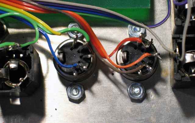
Now it’s time to solder the other end of the ribbon cables to their respective jacks.
First figure out which jacks are which. If you’ve got the PCB and panel orientated as shown in the above photo, then the X0 jack is the top right jack, and X1, X2, and X3 are below that. On the left side of the box are jacks X4, X5, X6, and X7. The row of 8 jacks on the top of the box are Y0 (rightmost) through Y7 (leftmost). You might want to label each jack with a sharpie on the back side of the panel. Like this photo:

Now that you know which jack is which, and which ribbon cable goes to which section of jacks, you can start soldering them as follows:
- Y0-Y3 cable:
- Y0: Brown
- Y1: Orange
- Y2: Green
- Y3: Purple
- X0-X3 cable:
- X0: Blue
- X1: Yellow
- X2: Red
- X3: Black
- X4-X7 cable:
- X4: Blue
- X5: Yellow
- X6: Red
- X7: Black
- Y4-Y7 cable:
- Y4: Brown
- Y5: Orange
- Y6: Green
- Y7: Purple
Note that you only need to solder every other wire. The un-soldered wires can be snipped just barely shorter than their neighboring wire.
11) If you’re using this solely for routing audio signals (not circuit bending), then to reduce noise you should put a “pull-down” resistors on the signal pins on your jacks. A 47k resistor on each of the 16 jacks will work great. The resistor is soldered directly on the jack between the signal pin (where the wire connects to the jack) and the jack’s ground pin.
[ photo coming soon ]
12) In a similar fashion, connect the 6-pin connector to the MIDI header:
... and solder 5 of those wires to the two MIDI jacks (the yellow wire is not used and should be snipped so that it won’t short anything out):
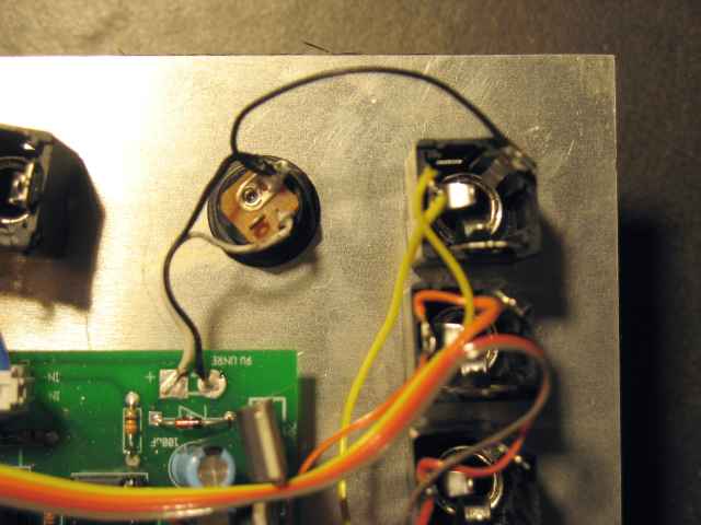
13) Wire in the power jack with three wires: One to power on the board (white), one to ground on the board (black), and one to ground on a neighboring jack (black).
This last one grounds the power jack and board to the metal panel itself– if you’re not using a metal panel [e.g. mounting inside an acoustic guitar], then you will need to run a ground wire to each jack.
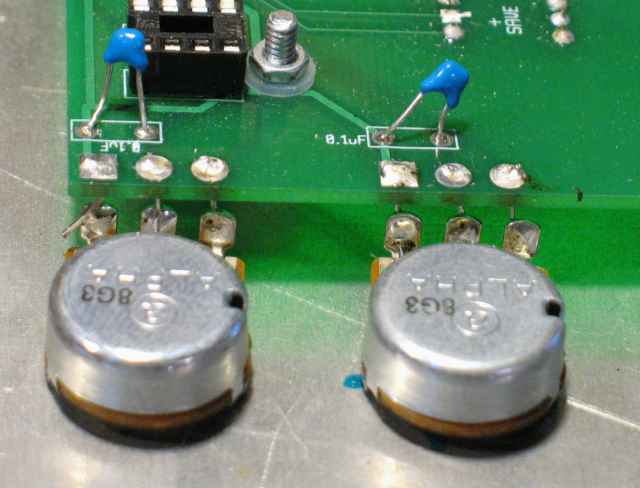
14) Wire the pots using scraps of small wire:
FIRE IT UP
15) Put in all the ICs except the ATMEGA32 and the MT8816. Make sure to line up the notch or dot on the IC with the notch on the socket (which should be lined up with the notch on the board silkscreen). If you’re sketched out about your build quality, you can play it safe by putting in just a few ICs at a time.

16) Power it up. Have a multimeter handy to test the voltage. Put the black lead on ground (to the metal panel, or the power jack), and use the red lead to measure these voltages:
- ATMEGA32 pin 10: 5V
- ATMEGA32 pin 11: 0V
- ATMEGA32 pin 30: 5V
- ATMEGA32 pin 31: 0V
- MT8816 pin 40: 5V (or 9V if you jumpered for that)
- MT8816 pin 20: -5V (or -9V if you jumpered for that)
- MT8816 pin 16: 0V
17) If your voltages are correct, power it down and insert the two 40-pin ICs:
18) Power it back up. It should light up right away and come to life! If not, power it down and check around. Measure the voltages from step 15 again, make sure no ICs are backwards.

19) Congratulations! You have a new Bend Matrix! Now pry your eyeballs away from the flashing animated lights and go to the Bend Matrix forum to post your success!! Welcome to the club!